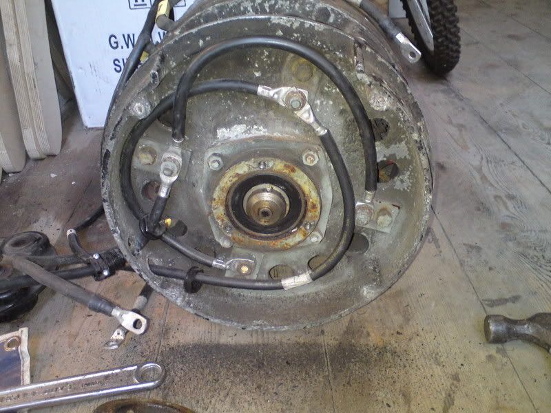
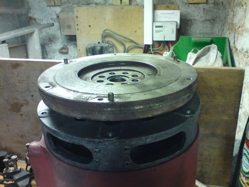
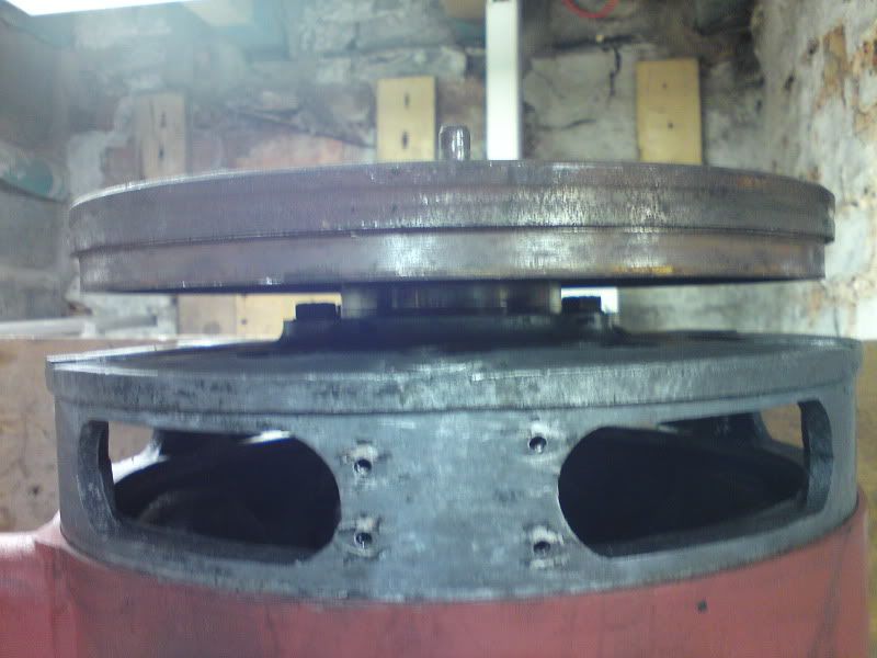
I picked up a really big motor for the MR2. Well, I just got it because it was £100 and 12" diameter and working.
It is an old 72v milk float motor, a Morrisons MD5
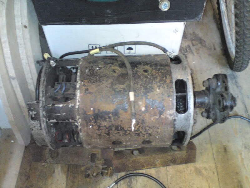
![Image](http://i5.photobucket.com/albums/y179/Eversley/Motors/DSC00662.jpg)
![Image](http://i5.photobucket.com/albums/y179/Eversley/Motors/DSC00663.jpg)
It runs like this.
![Image](http://i5.photobucket.com/albums/y179/Eversley/Motors/th_BenchTest01.jpg)
![Image](http://i5.photobucket.com/albums/y179/Eversley/Motors/DSC00670.jpg)
![Image](http://i5.photobucket.com/albums/y179/Eversley/Motors/DSC00668.jpg)
![Image](http://i5.photobucket.com/albums/y179/Eversley/Motors/DSC00679.jpg)
![Image](http://i5.photobucket.com/albums/y179/Eversley/Motors/DSC00680.jpg)
![Image](http://i5.photobucket.com/albums/y179/Eversley/Motors/DSC00674.jpg)
![Image](http://i5.photobucket.com/albums/y179/Eversley/Motors/DSC00675.jpg)
![Image](http://i5.photobucket.com/albums/y179/Eversley/Motors/DSC00683.jpg)
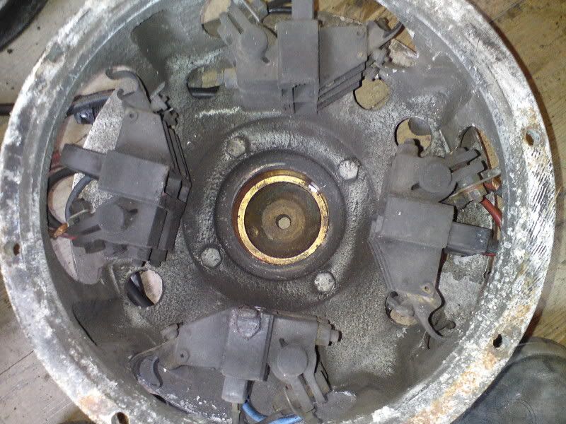
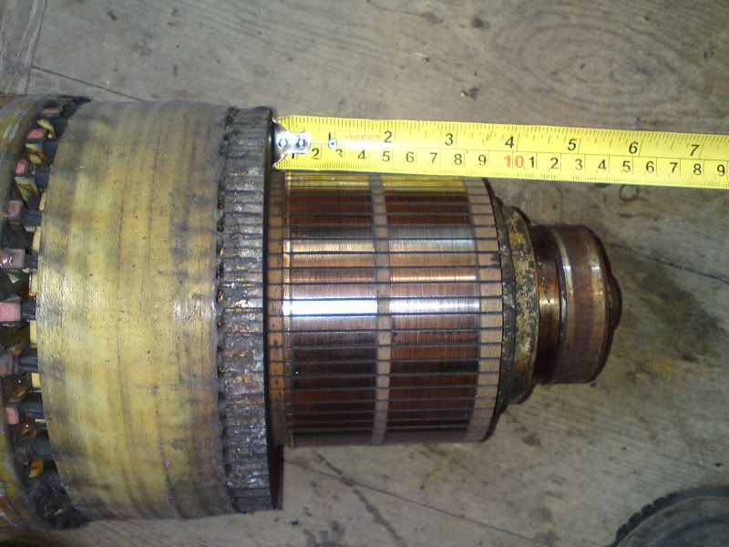
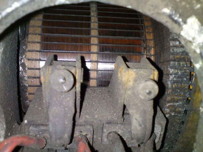
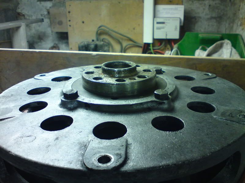
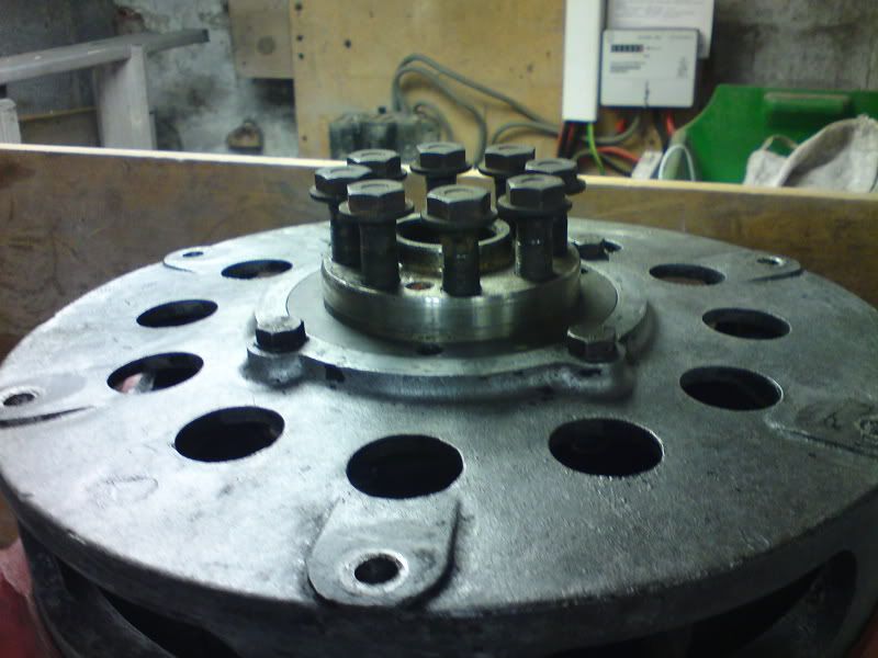
There are a couple of cracks through two of the comm end mounting bolt holes but I don't think they will be a problem unless I need to advance the brushes.
![Image](http://i5.photobucket.com/albums/y179/Eversley/Motors/DSC00686.jpg)
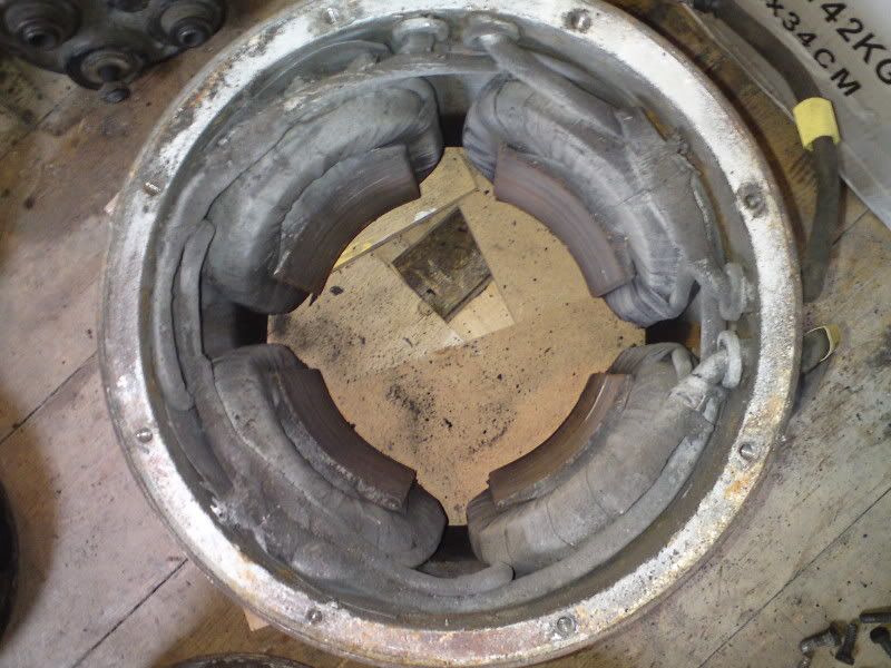
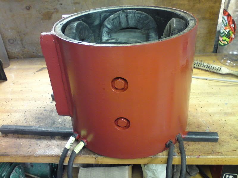
I really like the art Deco look of the drive end.
![Image](http://i5.photobucket.com/albums/y179/Eversley/Motors/DSC00684.jpg)
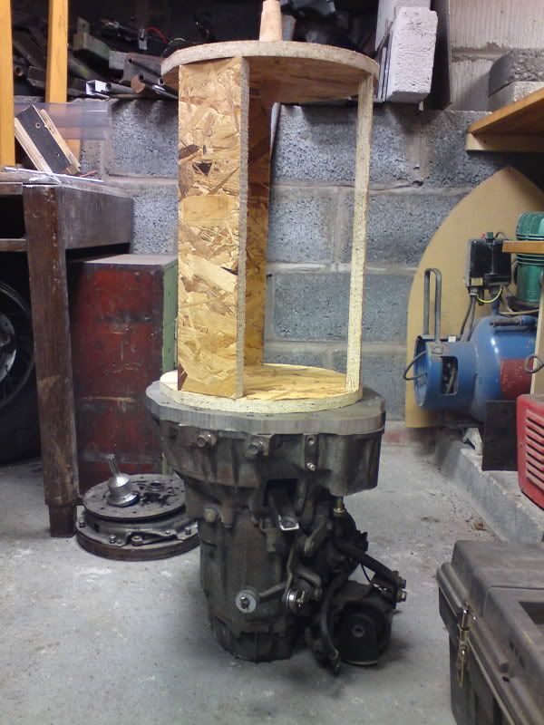
I have started cleaning and painting, just red oxide for now until I can decide on a colour.
![Image](http://i5.photobucket.com/albums/y179/Eversley/Motors/DSC00682.jpg)
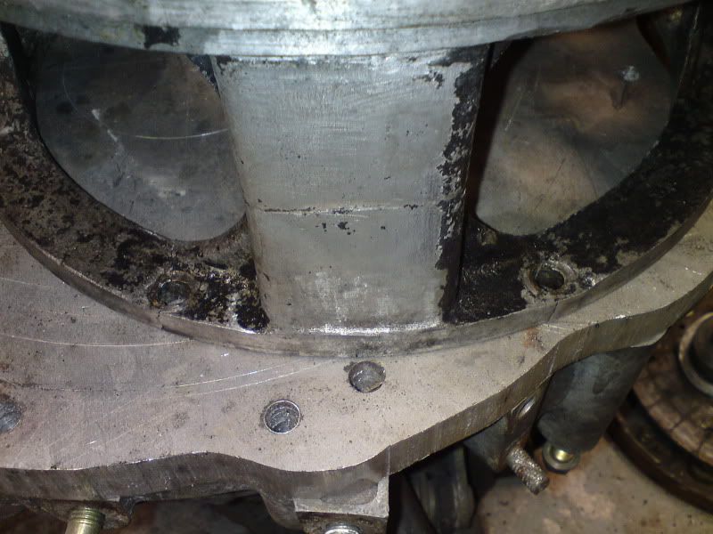
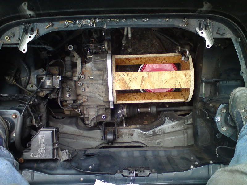
This is how it fits on the gearbox using a wooden mock up.
![Image](http://i5.photobucket.com/albums/y179/Eversley/MR2%20EV/MR2104.jpg)
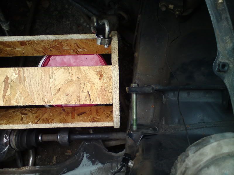
CV joint clearance is an issue but I am trying to solve that.
![Image](http://i5.photobucket.com/albums/y179/Eversley/MR2%20EV/MR2106.jpg)
It is a tight fit in the engine bay too.
![Image](http://i5.photobucket.com/albums/y179/Eversley/MR2%20EV/MR2111.jpg)
![Image](http://i5.photobucket.com/albums/y179/Eversley/MR2%20EV/MR2112.jpg)
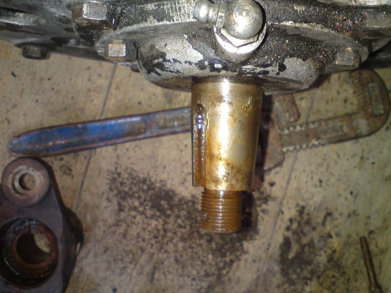
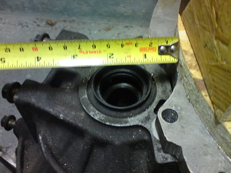
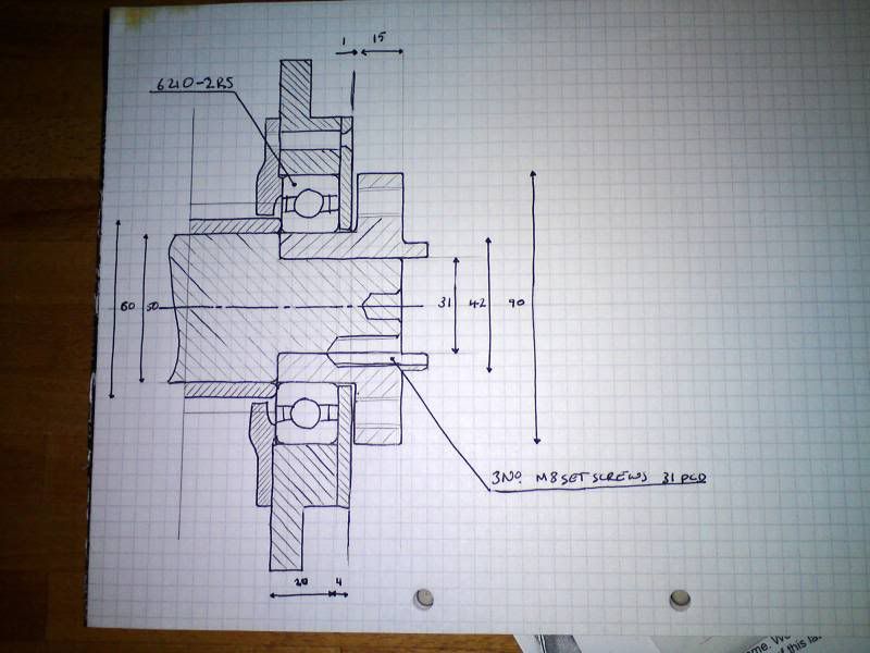
So I need to have a very short adaptor that will look like this.
![Image](http://i5.photobucket.com/albums/y179/Eversley/MR2%20EV/MR2107.jpg)
![Image](http://i5.photobucket.com/albums/y179/Eversley/MR2%20EV/MR2108.jpg)
![Image](http://i5.photobucket.com/albums/y179/Eversley/MR2%20EV/MR2109.jpg)
![Image](http://i5.photobucket.com/albums/y179/Eversley/MR2%20EV/MR2110.jpg)
What I will do is to use a larger shaft bearing and incorporate the coupler inside the bearing.
![Image](http://i5.photobucket.com/albums/y179/Eversley/MR2%20EV/DSC00736.jpg)
However, after all this preperation I have no idea if the motor is even going to be suitable.
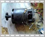
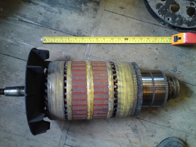
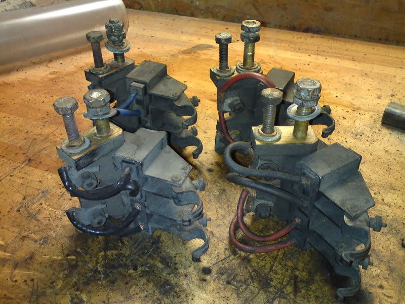
It has six cables like this.
![Image](http://www.diyelectriccar.com/forums/attachment.php?attachmentid=6265&d=1270414170)
I have tested like this.
Test 1: Connect F to battery positive, E to A, and B to battery negative. Note direction of rotation.
Test 2: Connect F to battery positive, E to J, and H to battery negative. Note direction of rotation.
Results:
Test 1: Clockwise seen from comm end, 965rpm.
Test 2: Clockwise seen from comm end, 925rpm.
Any thoughts on how best to connect the motor or what else I need to test or measure?