Old BMS General Thread

Threads relating to the BMS system begun by Peter Perkins

Moderators: GregsGarage, retepsnikrep

mikep_95133
Posts: 28
Joined: Thu Sep 25, 2008 6:38 pm

Postby mikep_95133 » Mon Oct 13, 2008 3:26 am

retepsnikrep wrote:I agree it's an obscure Picaxe editor bug as the text always looks fine. No one reported this problem with the earlier version so it's a bit annoying.

Anyway you can just delete the REMED text or do some backspace hopscotch to get rid of what must be a hidden character causing the error :roll:

mikep_95133 wrote:Greg was also right that the power has to be off to the Slave board when the Picaxe Editor is first told to run. Then in the first couple of seconds, the power is then turned on and then the downloading to the Picaxe chip works fine.


This is not consistently true though :? for my 50 digital slaves it's not true at all as they see the download straight away and don't have to be powered off as described. Very odd but I suspect it's to do with the cheapo serial download system used which does not comply with the Serial PC standards but works on most machines (PC's) and is a bit of a fudge.

An enhanced serial download circuit is described in the Picaxe documentation, that may be more reliable, but I havent tried it.


I wonder how your slaves would program using the Analog software? I'll try the enhanced circuit to see how it does.

Mike

User avatar
retepsnikrep
Posts: 1387
Joined: Sat May 26, 2007 4:50 pm
Location: North Yorkshire England
Contact:

Postby retepsnikrep » Mon Oct 13, 2008 3:31 am

Mike

I think it's more likely due to inconsistencies between implementations of the serial hardware/protocol on the PC. There are thousands of motherboards with different serial chips.

My garage machine used to program the Pic's is a very old 300mhz thing running Win98SE.

Of course your testing may reveal all.

Look's like someone has come up with a clone for the Picaxe chips :roll: Interesting and may help to keep the original Picaxe maker Reved on their toes. I have no idea if the BMS software written so far works on these clones :wink: Be my guest though :)

http://www.kicchip.co.uk/

The program editor looks quite nice though, perhaps Reved can clone that :lol:
Regards Peter

Two MK1 Honda Insight's. One running 20ah A123 Lithium pack. One 8ah BetterBattery Nimh pack.
One HCH1 Civic Hybrid running 60ah A123 Lithium pack.

mikep_95133
Posts: 28
Joined: Thu Sep 25, 2008 6:38 pm

Postby mikep_95133 » Mon Oct 13, 2008 3:40 am

retepsnikrep wrote:Mike

I think it's more likely due to inconsistencies between implementations of the serial hardware/protocol on the PC. There are thousands of motherboards with different serial chips.

My garage machine used to program the Pic's is a very old 300mhz thing running Win98SE.

Of course your testing may reveal all.

Look's like someone has come up with a clone for the Picaxe chips :roll: Interesting and may help to keep the original Picaxe maker Reved on their toes. I have no idea if the BMS software written so far works on these clones :wink: Be my guest though :)

http://www.kicchip.co.uk/

The program editor looks quite nice though, perhaps Reved can clone that :lol:


Did you try them with the Analog code?

Mike

User avatar
retepsnikrep
Posts: 1387
Joined: Sat May 26, 2007 4:50 pm
Location: North Yorkshire England
Contact:

Postby retepsnikrep » Mon Oct 13, 2008 3:44 am

Yes but only one prototype, and thats quite a few weeks ago now, I don't remember any issues.
Regards Peter

Two MK1 Honda Insight's. One running 20ah A123 Lithium pack. One 8ah BetterBattery Nimh pack.
One HCH1 Civic Hybrid running 60ah A123 Lithium pack.

centrex
Posts: 9
Joined: Sat Oct 11, 2008 9:47 pm
Location: Sydney Australia

Postby centrex » Tue Oct 14, 2008 9:08 am

Hi Peter
I have just been looking at the software below and I am wondering about a bit of the code.

[quote="retepsnikrep"]Master and Slaves running at 2400 baud data comms for 12hrs,

www.solarvan.co.uk/bms/SLAVEDIGITAL0710 ... 00BAUD.txt

The section just after Interupt: you make VData = 0 then after Loop1: you transmit VData as part of the serout command but you never update VData to equal the Cell voltage.
Am I missing something.
regards
Centrex

User avatar
retepsnikrep
Posts: 1387
Joined: Sat May 26, 2007 4:50 pm
Location: North Yorkshire England
Contact:

Postby retepsnikrep » Tue Oct 14, 2008 9:59 am

centrex wrote:Am I missing something.
regards
Centrex


Yes but it's a bit complicated. I hope you can follow my explanation.

The variable CellVoltage is a 16 bit word made up of two byte variables b0 (VData) and b1 (Not defined). I used a 16 bit word to allow me the full resolution of the 10bit READADC10 input command. I could have used the 8bit READADC command, but would have lost a lot of resolution, however the code would have been simpler.

In order to save time I only transmit one byte of info back to the Master (VDATA) this covers a 0-2.55v range.

In order to get a valid single byte value to transmit back to the Master I subtract 175 from CellVoltage, which leaves a result that fits into the single lower byte of the word CellVoltage, and is the byte VData :wink: This is transmitted and the Master adds 175 back to it to re-create the actual voltage in the Master word variable CellVoltage. :wink:

So if the cell voltage was say 4.00V this would be 400 in the Slave CellVoltage word variable, minus 175 = 225 which is stored in the lower byte VData, and transmited to the Master. The Master receives this into VData which again is the lower byte of the word variable CellVoltage and adds 175 to it to get the original voltage in the word CellVoltage.

The single byte data method gives a useful cell voltage range of 1.75 (175) to 4.30 (430) Volts, anything outside this is treated as an error by the Slave, and VData is set to 0 so the Master can detect it.

I hope that helps.

You will see the Slave If/Then test checks wether the CellVoltage is outside the permitted range due to a problem, and sets VData to 0 so the Master can say "Houston we have a problem" when it receives it :shock:

Edit

Just a few pics of the bms screen and buttons installation into the little cubby hole in my Insight. I'm not convinced it's in as good a spot as the little screen would have been on the dashboard, but it is certainly discrete and less likely to encourage theft/breakin.

www.solarvan.co.uk/bms/CubbyHoleDisplay1.jpg
www.solarvan.co.uk/bms/CubbyHoleDisplay2.jpg
www.solarvan.co.uk/bms/CubbyHoleDisplay5.jpg
www.solarvan.co.uk/bms/CubbyHoleDisplay6.jpg

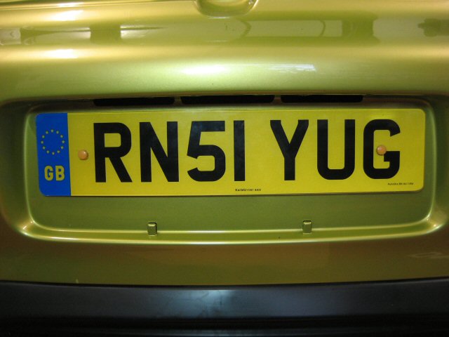
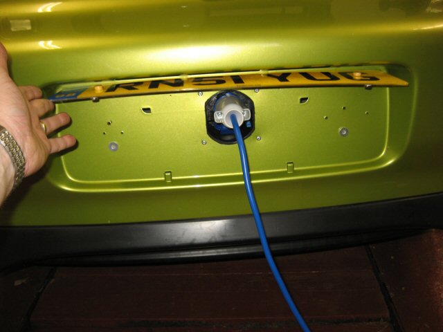
Pics of rear 16A charging socket behind hinged number plate with magnetic fastners.

www.solarvan.co.uk/insight/chargesocket1.jpg
www.solarvan.co.uk/insight/chargesocket4.jpg

Need to do some testing on the menu buttons now, but it seems to be working OK so far :)

The slightly higher (intentional) centre opaque led is an extension led from the Zivan NG3 charger and changes colour according to the point in the charge cycle. Red (Charging), Yellow (Nearly done), Green (Finished)

Latest Master software with enhanced buttons and new speed/distance routine seems to work ok. Thanks Matt & Jeremy. Happy now Roger :lol:

www.solarvan.co.uk/bms/MASTER141008_V42_2400BAUD.txt
Last edited by retepsnikrep on Wed Oct 15, 2008 5:03 am, edited 5 times in total.
Regards Peter

Two MK1 Honda Insight's. One running 20ah A123 Lithium pack. One 8ah BetterBattery Nimh pack.
One HCH1 Civic Hybrid running 60ah A123 Lithium pack.

User avatar
qdos
Posts: 2089
Joined: Fri Apr 27, 2007 10:26 pm
Location: Dorset
Contact:

Postby qdos » Tue Oct 14, 2008 10:10 pm

Very tidy Peter very tidy indeed Well done.

centrex
Posts: 9
Joined: Sat Oct 11, 2008 9:47 pm
Location: Sydney Australia

Postby centrex » Wed Oct 15, 2008 7:53 am

Hi Peter
That all makes sense, I just hadnt thought about in those terms.
Pictures of the display etc look very neat.
regards
Centrex

User avatar
retepsnikrep
Posts: 1387
Joined: Sat May 26, 2007 4:50 pm
Location: North Yorkshire England
Contact:

Postby retepsnikrep » Wed Oct 15, 2008 2:29 pm

Just a litle update, tweaked my display install and seperated video signal from within the multi core lead I used initially, it was functional but a bit noisy, now it looks crystal clear with separate ground and signal wires and a nice HQ coax cable and gold plated connectors 8) Might as well get it right. Image

Two pics showing driving position and display/control, and another youtube video when it's finished uploading explaining it a bit more :roll:

www.solarvan.co.uk/insight/DisplayInstall1.jpg

www.solarvan.co.uk/insight/DisplayInstall2.jpg

Hopefully better audio quality this time on video as I changed encoder setting from Cheapskate 64kb to Imprudent 128kb :lol:

http://www.youtube.com/watch?v=SBYJXj4pUrk

Master current consumption testing on the BMS also quite comforting.

With screen on it's about 185ma from 12v supply

With screen off it's about 90ma from 12v supply

Once it's driving the charging relay that will rise a bit, but not bad and capable of running from the Car pb battery without much risk of flattening it unless left on for a week or so.

Edit Sorry the audio is not better I'll keep fiddling with that, however the new watch in high quality link on youtube does work and it's a much better picture.
Regards Peter

Two MK1 Honda Insight's. One running 20ah A123 Lithium pack. One 8ah BetterBattery Nimh pack.
One HCH1 Civic Hybrid running 60ah A123 Lithium pack.

mikep_95133
Posts: 28
Joined: Thu Sep 25, 2008 6:38 pm

Postby mikep_95133 » Wed Oct 15, 2008 6:11 pm

Peter,

Did you have to remove the LCD from it's factory housing to mount it into your Insight? I'm looking ahead to the same idea of a clean mounting of the LCD.

Mike


Return to “BMS thread”

Who is online

Users browsing this forum: No registered users and 2 guests