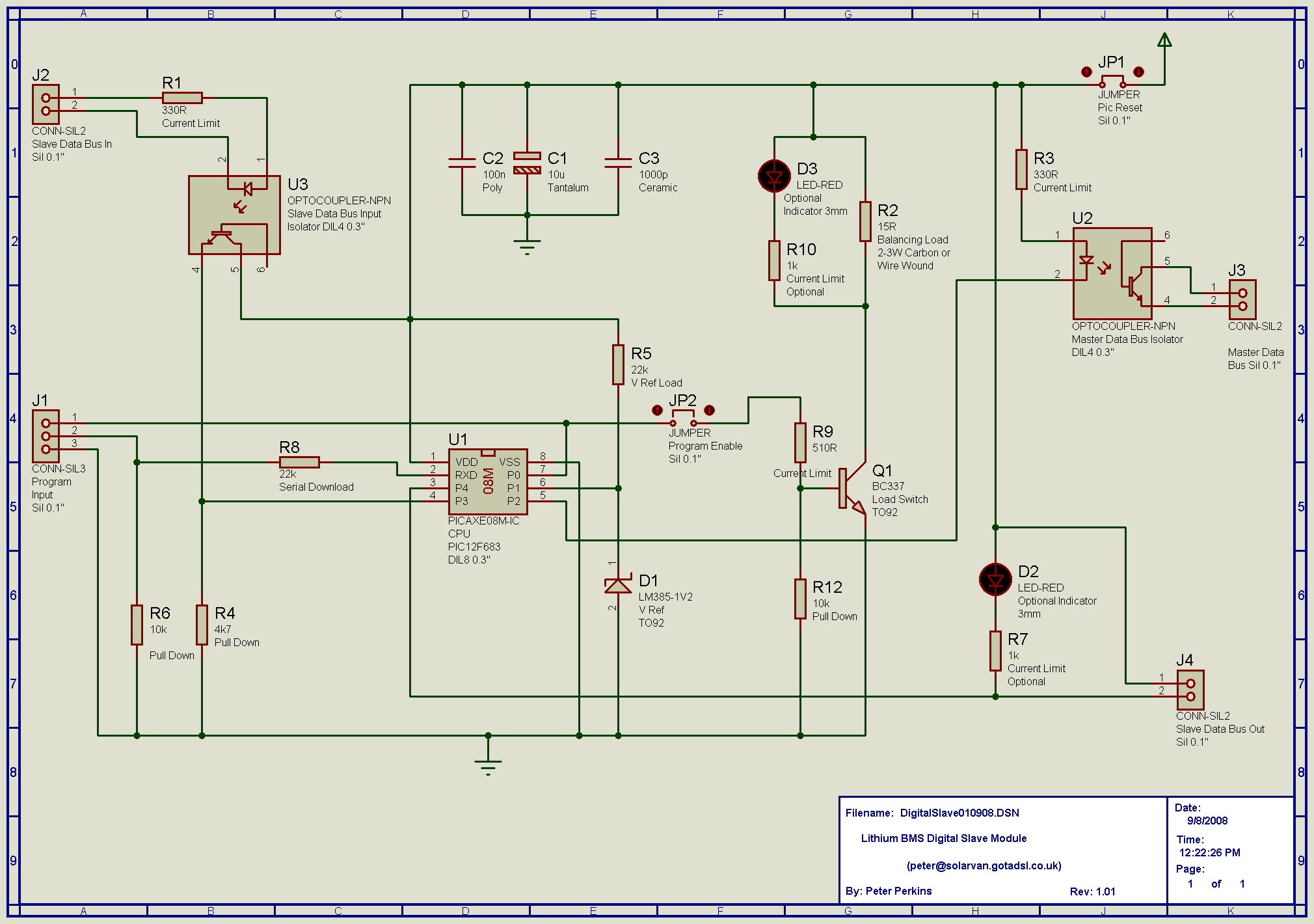
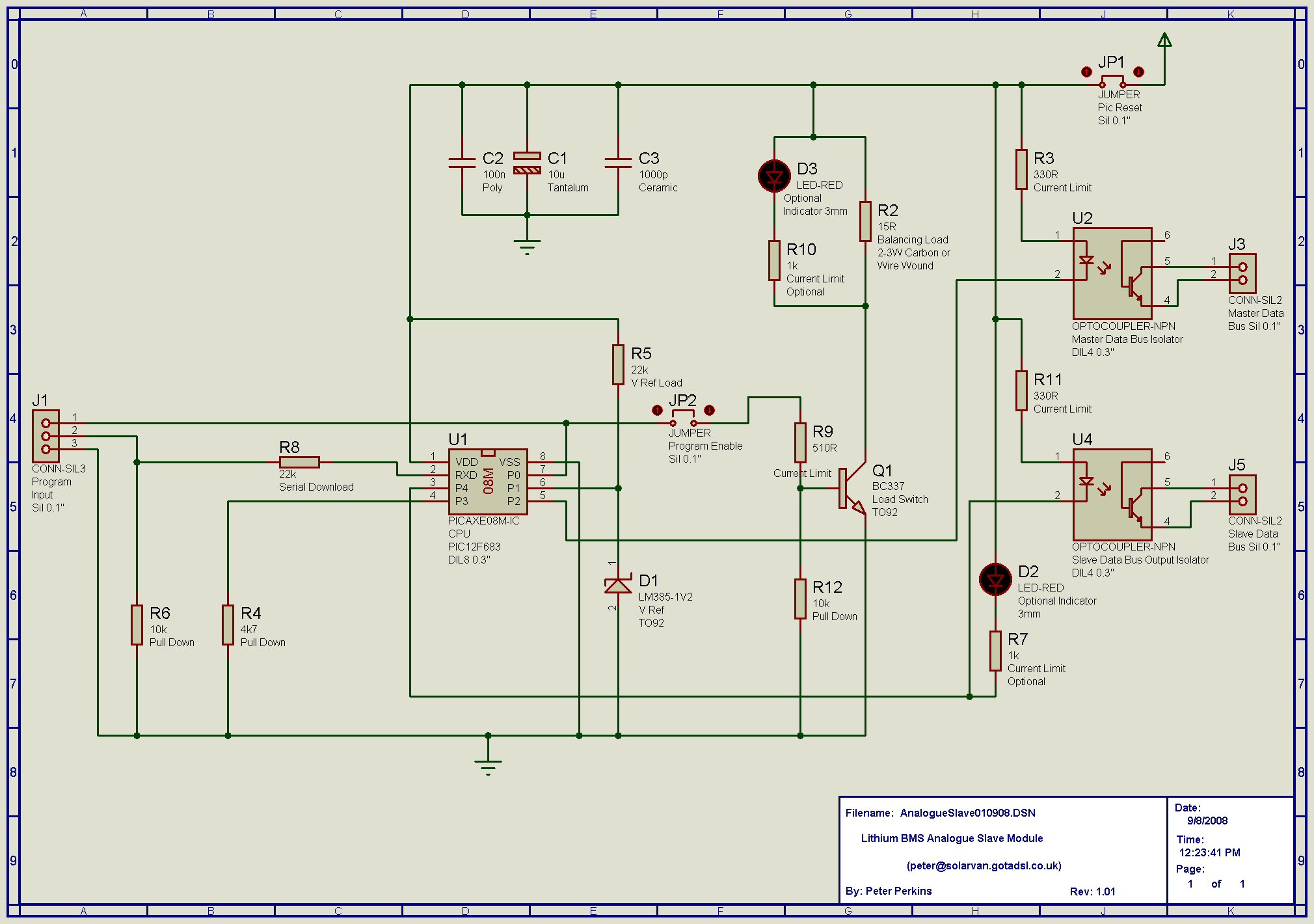
Been thinking about the easiest way to convert my analogue slave boards to digital, so that I can implement the analogue digital slave software and maybe later full digital software. First, a repost of the 2 schematics for the different boards.
http://www.solarvan.co.uk/bms/DigitalSlave080908.jpg
http://www.solarvan.co.uk/bms/AnalogueSlave080908.jpg
Normally to convert the boards would require moving components R11,U4 and J5, on the analogue schematic, to position R1,U3 and J2 on the digital schematic. But I think I can do the same thing by just adding J2 to my analogue slave boards, but connecting it to position U3, pins 4&5 as shown on the digital schematic. The isolation board to board is preserved and should run any digital software unmodified. If I have made a mistake in my thinking here, please let me know.
Greg
Old BMS General Thread
Moderators: GregsGarage, retepsnikrep
-
GregsGarage
- Posts: 870
- Joined: Tue Apr 01, 2008 5:27 pm
- Location: Galashiels, Scottish Borders
- Contact:
-
retepsnikrep

- Posts: 1387
- Joined: Sat May 26, 2007 4:50 pm
- Location: North Yorkshire England
- Contact:
Greg
That might work for most of the slaves, but not for the first in the chain which has to be isolated from the Master signals coming in at J2.
Try it by all means. I suggest you make up the Master first though and test a couple, if you get reliable comms then fine do them all with your new configuration. You don't want to do 30 and find they don't work. All I can say about my digital ones was they worked fine on the bench, only my poor layout and inter cell wiring in the noisy environment prevented it from working straight away when installed.
Peter
Regards Peter
Two MK1 Honda Insight's. One running 20ah A123 Lithium pack. One 8ah BetterBattery Nimh pack.
One HCH1 Civic Hybrid running 60ah A123 Lithium pack.
Two MK1 Honda Insight's. One running 20ah A123 Lithium pack. One 8ah BetterBattery Nimh pack.
One HCH1 Civic Hybrid running 60ah A123 Lithium pack.
-
GregsGarage
- Posts: 870
- Joined: Tue Apr 01, 2008 5:27 pm
- Location: Galashiels, Scottish Borders
- Contact:
pics of propsed slave board update
Peter,
Here is a pic of the analogue slave layout as I have built.

So I want to convert to the digital software but I am lazy, don't like the idea of moving 3 components on 24 slave boards, so I have come up with this plan.

By adding R1, J2 and 2 jumpers, this board should run all of the software you have written so far. One board design for the original analogue slave software, digital software and an your latest analogue on digital board software. Like I said, I originally intended this as a cheat to upgrade my board but I think this idea could have potential for version 2 of the slave boards. I can make the modifications and still run my current software, so no risk that I will break my current setup, because I am not disabling any existing functions.
You mentioned needing an extra opto on the first board for connecting to the master, easily done. Just replace the 2 jumpers for an opto at U3!
Since J4 is no longer used it shouldn't cause a problem having 3 optos on the board, you had expressed concern about this in the past when we discussed upgrading the boards to digital.
Also I have noticed a possible weakness in the existing digital layout. J4 doesn't have a 330R current limiting resistor, that resistor is found on the opto on the next board or master it connects to. That works fine, but say both terminals on J4 get shorted together (or more likely, the wiring) you will be feeding full cell voltage to the pic. It won't last long if it tries to sink that current. I know it's all hypothetical, but I have seen stranger things happen. With my proposal the current limit resistor is on the same board, so should be safer. Final thought, I believe you have an opto on the master that connects to J4 of the last board. That will need to be removed since the last board has the opto on it.
Oh, did I mention I was looking for the lazy option. Will probably do this;


Here is a pic of the analogue slave layout as I have built.
So I want to convert to the digital software but I am lazy, don't like the idea of moving 3 components on 24 slave boards, so I have come up with this plan.
By adding R1, J2 and 2 jumpers, this board should run all of the software you have written so far. One board design for the original analogue slave software, digital software and an your latest analogue on digital board software. Like I said, I originally intended this as a cheat to upgrade my board but I think this idea could have potential for version 2 of the slave boards. I can make the modifications and still run my current software, so no risk that I will break my current setup, because I am not disabling any existing functions.
You mentioned needing an extra opto on the first board for connecting to the master, easily done. Just replace the 2 jumpers for an opto at U3!
Since J4 is no longer used it shouldn't cause a problem having 3 optos on the board, you had expressed concern about this in the past when we discussed upgrading the boards to digital.
Also I have noticed a possible weakness in the existing digital layout. J4 doesn't have a 330R current limiting resistor, that resistor is found on the opto on the next board or master it connects to. That works fine, but say both terminals on J4 get shorted together (or more likely, the wiring) you will be feeding full cell voltage to the pic. It won't last long if it tries to sink that current.
Oh, did I mention I was looking for the lazy option. Will probably do this;
Greg Fordyce
Daewoo Matiz
http://www.evalbum.com/4191
Daewoo Matiz
http://www.evalbum.com/4191
-
GregsGarage
- Posts: 870
- Joined: Tue Apr 01, 2008 5:27 pm
- Location: Galashiels, Scottish Borders
- Contact:
I modified my spare slave as per the picture directly above, and have taken Peters software and modified it so that it now outputs both high and low cell warnings on the same opto U4/J5.
Original version here;
http://www.solarvan.co.uk/bms/ANALOGUESLAVE_DIGITALPCB_211208_V01.TXT
My changes are in this snippet, marked with *
Top tip, if you are posting code, use the check box below the editing window to disable HTML in post.
Tested the software on my spare slave and works as intended. My management module will now be able to carry out a self test on all the slaves as a automatic ignition key on test and also when the battery charger is connected. It will then wait till it sees a cell warning, determine what is happening at that moment, either charging, driving or regen and take appropriate action. By knowing what is happening when you get a cell voltage warning will tell you if it is a over voltage or under voltage warning.
As an added bonus I can now see which board is triggering a high or low cell warning, simply by following the leds back until I find the first one that is lit. Or if it fails the key on test, follow the leds forward till you find the one that isn't lit. My slaves will also now be able to run the full digital software if I decide to use that later without any modifications and I can always fall back to simple analogue mode by simply reprogramming them.
J3 and U2 is not being used in this version, but I can leave the wiring intact for digital upgrade. Or J3 and U2 could be used as a absolute max/min voltage cutoff. Peter and myself have set the uper and lower voltage cutoffs well within the manufactures specs. But, for example J3/U2 could be set to trigger at 3.85 volts per cell and used to fully turn off the charger, a kind of safety net.
Original version here;
http://www.solarvan.co.uk/bms/ANALOGUESLAVE_DIGITALPCB_211208_V01.TXT
My changes are in this snippet, marked with *
Code: Select all
   if CellV > MaxVOptoOn then
*   low LowOpto
   endif

*;   if CellV < MaxVOptoOff then
*;   high HighOpto
*;   endif

   if CellV > LoadOn then
   high Load
   endif

   if CellV < LoadOff then
   low Load
   endif

   if CellV < MinVOptoOn or pin3 = 1 then
   low LowOpto
   endif

*   if CellV > MinVOptoOff and CellV < MaxVOptoOff and pin3 = 0 then
   high LowOpto
   endif

   goto Main
Top tip, if you are posting code, use the check box below the editing window to disable HTML in post.
Tested the software on my spare slave and works as intended. My management module will now be able to carry out a self test on all the slaves as a automatic ignition key on test and also when the battery charger is connected. It will then wait till it sees a cell warning, determine what is happening at that moment, either charging, driving or regen and take appropriate action. By knowing what is happening when you get a cell voltage warning will tell you if it is a over voltage or under voltage warning.
As an added bonus I can now see which board is triggering a high or low cell warning, simply by following the leds back until I find the first one that is lit. Or if it fails the key on test, follow the leds forward till you find the one that isn't lit. My slaves will also now be able to run the full digital software if I decide to use that later without any modifications and I can always fall back to simple analogue mode by simply reprogramming them.
J3 and U2 is not being used in this version, but I can leave the wiring intact for digital upgrade. Or J3 and U2 could be used as a absolute max/min voltage cutoff. Peter and myself have set the uper and lower voltage cutoffs well within the manufactures specs. But, for example J3/U2 could be set to trigger at 3.85 volts per cell and used to fully turn off the charger, a kind of safety net.
Greg Fordyce
Daewoo Matiz
http://www.evalbum.com/4191
Daewoo Matiz
http://www.evalbum.com/4191
-
retepsnikrep
- Posts: 1387
- Joined: Sat May 26, 2007 4:50 pm
- Location: North Yorkshire England
- Contact:
Well done Greg.
I intend getting my arse in gear in next couple of weeks to relocate my cells and get things all tidied up including getting Master Working!! I've been revelling in my high mpg but got sidetracked as you do
Just busy helping other Insight Owners this week!
For info there is one for sale on e-bay
http://cgi.ebay.co.uk/ws/eBayISAPI.dll? ... 0367080428
Regards Peter
Two MK1 Honda Insight's. One running 20ah A123 Lithium pack. One 8ah BetterBattery Nimh pack.
One HCH1 Civic Hybrid running 60ah A123 Lithium pack.
Two MK1 Honda Insight's. One running 20ah A123 Lithium pack. One 8ah BetterBattery Nimh pack.
One HCH1 Civic Hybrid running 60ah A123 Lithium pack.
-
GregsGarage
- Posts: 870
- Joined: Tue Apr 01, 2008 5:27 pm
- Location: Galashiels, Scottish Borders
- Contact:
Peters slaves provide 2 outputs. In digital mode one output provides cell data and the other provides slave bus communication. In analogue mode one output provides a low voltage warning and the other high voltage warning. The digital mode requires a master control board and the analogue mode is intended as a stand alone system. At the moment both Peter's and my systems are operating in analogue mode and only give us a warning but won't actually stop us from driving.
Recently Peter got the analogue software to operate on the digital slaves. This means he/we can switch between the analogue and digital system without having to modify the slaves or alter the wiring, just reprogram them and add the master board. I then proposed that one output could be used as both high and low voltage warning. This output could be connected to your charger and dash warning and half speed input that some controllers provide to warn and cut back power when the cells are near their limit. We are using 2.4v and 3.75 volts for the warning and charger cutback. That leaves a second output doing nothing, so that could be connected to a charger absolute cut-off (3.85 volts) and a controller absolute cut-off (2.0 volts). This system would give you a warning that cells are getting low before completely cutting the drive, which could be dangerous in a car. And it can be implemented as a stand alone system with no master module or even my EV Managment Module that I have been working on.
I have modified the code some more, here is a snippet of the code that I have changed, you will need to cut out the relevant section in Peters code and paste this in, see link a couple of posts above.
I have tested this on my spare slave test board and it works. My next step is going to be modifying and reprogramming my slaves for my Fiat. I am also planning a bit of a rewire, mainly to tidy up and also to move my DC convertors to the front where the original 12v battery was. Peter, what software are you using for your schematics?
I think this offers some real potential. It gives a system that can both provide a warning when the cells are near their limit and then prevent damage when the cells reach their absolute limit by completely shutting down car or charger. And as a bonus, can be upgraded to the digital system quite easily.
Recently Peter got the analogue software to operate on the digital slaves. This means he/we can switch between the analogue and digital system without having to modify the slaves or alter the wiring, just reprogram them and add the master board. I then proposed that one output could be used as both high and low voltage warning. This output could be connected to your charger and dash warning and half speed input that some controllers provide to warn and cut back power when the cells are near their limit. We are using 2.4v and 3.75 volts for the warning and charger cutback. That leaves a second output doing nothing, so that could be connected to a charger absolute cut-off (3.85 volts) and a controller absolute cut-off (2.0 volts). This system would give you a warning that cells are getting low before completely cutting the drive, which could be dangerous in a car. And it can be implemented as a stand alone system with no master module or even my EV Managment Module that I have been working on.
I have modified the code some more, here is a snippet of the code that I have changed, you will need to cut out the relevant section in Peters code and paste this in, see link a couple of posts above.
Code: Select all
if CellV > 385 or CellV < 200 then
   low HighOpto
   endif

   if CellV < 385 and CellV > 200 then
   high HighOpto
   endif

   if CellV > LoadOn then
   high Load
   endif

   if CellV < LoadOff then
   low Load

   if CellV < MinVOptoOn or CellV > MaxVOptoOn or pin3 = 1 then
   low LowOpto
   endif

   if CellV > MinVOptoOff and CellV < MaxVOptoOff and pin3 = 0 then
   high LowOpto
   endif

   goto Main
I have tested this on my spare slave test board and it works. My next step is going to be modifying and reprogramming my slaves for my Fiat. I am also planning a bit of a rewire, mainly to tidy up and also to move my DC convertors to the front where the original 12v battery was. Peter, what software are you using for your schematics?
I think this offers some real potential. It gives a system that can both provide a warning when the cells are near their limit and then prevent damage when the cells reach their absolute limit by completely shutting down car or charger. And as a bonus, can be upgraded to the digital system quite easily.
Greg Fordyce
Daewoo Matiz
http://www.evalbum.com/4191
Daewoo Matiz
http://www.evalbum.com/4191
-
retepsnikrep
- Posts: 1387
- Joined: Sat May 26, 2007 4:50 pm
- Location: North Yorkshire England
- Contact:
Greg
My current software is
Analog Slave (with Analog Software)
www.solarvan.co.uk/bms/SlaveAnalogueOnO ... _v1_15.txt
This does not incorporate your changes
Digital Slave (with Analog software)
www.solarvan.co.uk/bms/ANALOGUESLAVE_DI ... 08_V01.TXT
This what I am using at present
Digital Slave (with Digital Software)
www.solarvan.co.uk/bms/SLAVESIMPLEDIGIT ... 00BAUD.TXT
This is what I will be using shortly when I get my cells relocated and wiring sorted.
Master Board
www.solarvan.co.uk/bms/MASTER170109_V95_2400BAUD.txt
This is what I am using at present for tetsing
Watchdog
www.solarvan.co.uk/bms/Watchdog290708_v04.txt
This is what I am using at present
BMS Config
www.solarvan.co.uk/bms/BmsConfig300908_v06.txt
This is used to obtain the device ID numbers for the DS18B20 I2C temp sensors and to test data comms.
Hope that helps
Peter
When I have the Master/digital sytem working I will update the project zip file in post 1 on page 1
Regards Peter
Two MK1 Honda Insight's. One running 20ah A123 Lithium pack. One 8ah BetterBattery Nimh pack.
One HCH1 Civic Hybrid running 60ah A123 Lithium pack.
Two MK1 Honda Insight's. One running 20ah A123 Lithium pack. One 8ah BetterBattery Nimh pack.
One HCH1 Civic Hybrid running 60ah A123 Lithium pack.
-
GregsGarage
- Posts: 870
- Joined: Tue Apr 01, 2008 5:27 pm
- Location: Galashiels, Scottish Borders
- Contact:
wiring plan
I have been sketching out a circuit diagram to implement my new analogue slave software. J2 on the first board will connect to a simple push button on the dash. Pressing that with the ignition on will test all slaves and should light my high/low battery warning if all is working as it should. The output from J5 on the last board will go to 2 poles of a 3 pole change over relay. This relay will be energized by mains supply and send J5 to the charger voltage trimmer. When any cell reaches 3.75 volts the charging current will be reduced until U4 stops conducting. When the mains power is removed the relay will connect J5 to high/low battery warning on the dash. I will then get a warning if any cell goes below 2.4 volts or above 3.75 volts. The last pole of this relay will open the circuit to the controller IGN/KSI terminal, preventing the car being driven while connected to the mains.
J3 will need to drive a 2 pole change over relay. I will be driving the relays with 24 volts and I think the optos are rated for 50ma, so that should work out to 1.2 watts. I have found a suitable relay with coils rated for 800mw. The relay will be wired with one pole connected to the mains lead to the charger and the other pole connected to the IGN/KSI terminal of the controller. If the voltage of any cell goes less than 2.0 or greater than 3.85 volts that opto (U2/J3) will conduct causing the relay to disconnect the charger and controller.
I will post a diagram when I get time and find a program I like for drawing it.
Peter, what program are you using to draw your schematics?
Anybody else have a favorite program for drawing scematics and wiring diagrams?
Greg Fordyce
Daewoo Matiz
http://www.evalbum.com/4191
Daewoo Matiz
http://www.evalbum.com/4191
-
retepsnikrep
- Posts: 1387
- Joined: Sat May 26, 2007 4:50 pm
- Location: North Yorkshire England
- Contact:
Greg
Is there still an opto on the board for your first slave J2 connection and dash switch. I don't like the idea of the cell/pack voltage being present at a small switch on the dash, I would reccomend that remains isolated and as far as possible the HV remains contained/isolated at the slave level.
I also think you might be pushing the optos a bit hard, I would recommend a simple transistor switch in between to allow more relay drive current. Don't forget diodes on relays.
I use the Picaxe VSM schematic and simulation program as it allows simulation of the circuit and picaxe chips in the schematic If you use the same program I can send you the design files and you can tweak the actual published schematics. We can then swap ideas very easily.
The program is available from the picaxe website. It's pretty sophisticated and I have only scratched the surface of it, I still dont understand half the protocols and busses/power/ground wiring logic
E-Mail me about this.
Peter
Is there still an opto on the board for your first slave J2 connection and dash switch. I don't like the idea of the cell/pack voltage being present at a small switch on the dash, I would reccomend that remains isolated and as far as possible the HV remains contained/isolated at the slave level.
I also think you might be pushing the optos a bit hard, I would recommend a simple transistor switch in between to allow more relay drive current. Don't forget diodes on relays.
I use the Picaxe VSM schematic and simulation program as it allows simulation of the circuit and picaxe chips in the schematic
The program is available from the picaxe website. It's pretty sophisticated and I have only scratched the surface of it, I still dont understand half the protocols and busses/power/ground wiring logic
E-Mail me about this.
Peter
Regards Peter
Two MK1 Honda Insight's. One running 20ah A123 Lithium pack. One 8ah BetterBattery Nimh pack.
One HCH1 Civic Hybrid running 60ah A123 Lithium pack.
Two MK1 Honda Insight's. One running 20ah A123 Lithium pack. One 8ah BetterBattery Nimh pack.
One HCH1 Civic Hybrid running 60ah A123 Lithium pack.
Who is online
Users browsing this forum: Majestic-12 [Bot] and 16 guests