here's what it looks like mounted to the PCB, there is a guy here in the US selling the little boards (empty) for 3 dollars each and said he has quite a few of them. the bus bar will be drilled and tapped, and the pcb held in place with nylon bolts. the great thing about this current sensor is that it can be adapted to measure virtually any current. it has a voltage output range of ~4.5 volts, which can be either 0+/-2.25 or 2.5+/-2.25, depending on how it's wired. current range calibration is handled by mounting it closer or farther from the bus bar (such as using a thicker or thinner PCB) and is also affected by the size of the bar (a wider bar seems to be less sensitive, and a narrower bar should be more sensitive.) Final calibration can be handled with software.
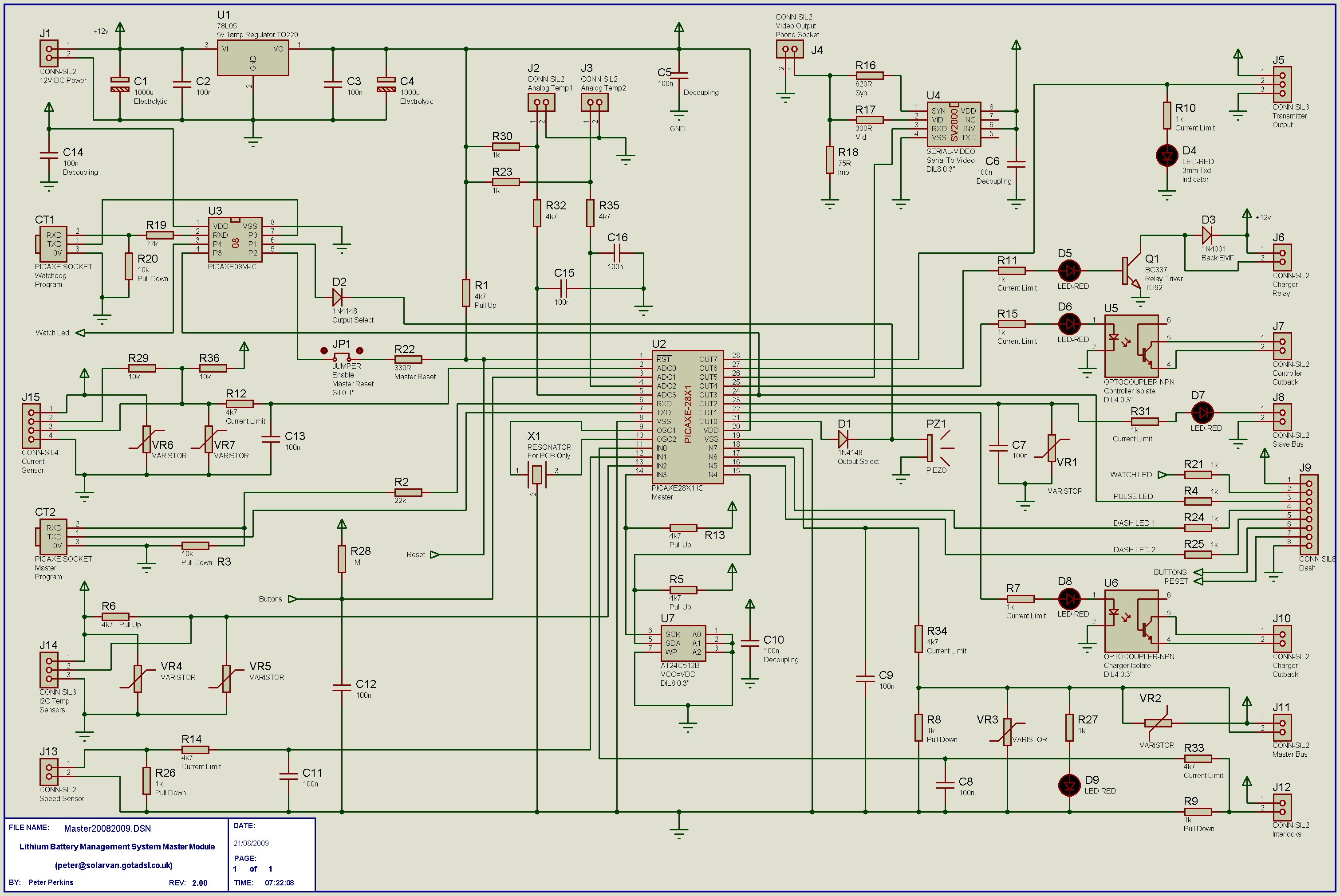
i'm looking at this schematic:
http://www.solarvan.co.uk/bms/Master20082009.jpg
and not completely sure what the function of R29 and R36 is. this current sensor only has three wires, instead of the 4 that are on the master board. it looks to me like R29 and R36 can both be eliminated, or pin 2 should be tied to pin 4 in order to keep from biasing the input signal.
We are going to use the "COUNT" function to count number of pulses that occur during a time period, which we will probably set to 250ms. we are planning to use a function generator to simulate an input signal until our working speed sensor arrives
Old BMS Software Thread
Moderators: GregsGarage, retepsnikrep
- retepsnikrep
- Posts: 1387
- Joined: Sat May 26, 2007 4:50 pm
- Location: North Yorkshire England
- Contact:
Re: Old BMS Software Thread
Yes you can eliminate R29 & R36.
I can't remember why i had those resistors
Regards Peter
Two MK1 Honda Insight's. One running 20ah A123 Lithium pack. One 8ah BetterBattery Nimh pack.
One HCH1 Civic Hybrid running 60ah A123 Lithium pack.
Two MK1 Honda Insight's. One running 20ah A123 Lithium pack. One 8ah BetterBattery Nimh pack.
One HCH1 Civic Hybrid running 60ah A123 Lithium pack.
-
- Posts: 100
- Joined: Sun Apr 03, 2011 7:41 pm
Re: Old BMS Software Thread
using the pre-built slave board you sent me, it works with my six test cells. but when i plug in the board that i built up, it's saying "cell three serial" error. i can go in and edit the number of cells down to 2 and it works fine, but it seems to have a problem with cell 3. but i can send command 7 and it will turn on each led for half a second, even when it's set to only 2 cells.
i tried reprogramming the pic on cell three but that didn't change anything. i'm curious as to how command seven can flash all six leds, if there's a serial error on cell three.
any ideas?
i tried reprogramming the pic on cell three but that didn't change anything. i'm curious as to how command seven can flash all six leds, if there's a serial error on cell three.
any ideas?
- retepsnikrep
- Posts: 1387
- Joined: Sat May 26, 2007 4:50 pm
- Location: North Yorkshire England
- Contact:
Re: Old BMS Software Thread
Commands to the slaves are sent over the slave bus and responses come over the master bus.
When the master is waiting for responses it doesn't know about any more slaves than you have told it, so it doesn't detect slaves sending responses above the number you set, but the command you sent will still pass through and be acted upon by all the active slaves.
You must set the number of cells to the number of active slaves.
Why? OK Lets imagine you have 16 active slaves (cells attached, powered and working) but you only tell the master you have 8. The master will only be expecting 8 responses, so as soon as it gets 8 responses it moves on and sends another command which the first cells will be responding to whilst the other 8 cells on that slave board are still responding to the previous command. This causes two slaves to be transmitting on the master bus at the same time. Result garbage and serial error.
Check the master bus opto on slave 3 on the board and associated resistors, right values, right way round etc.
Does it work set to three cells?
Does command 8 work? Report slave software version.
Regards Peter
Two MK1 Honda Insight's. One running 20ah A123 Lithium pack. One 8ah BetterBattery Nimh pack.
One HCH1 Civic Hybrid running 60ah A123 Lithium pack.
Two MK1 Honda Insight's. One running 20ah A123 Lithium pack. One 8ah BetterBattery Nimh pack.
One HCH1 Civic Hybrid running 60ah A123 Lithium pack.
-
- Posts: 100
- Joined: Sun Apr 03, 2011 7:41 pm
Re: Old BMS Software Thread
changed the opto, checked continuity between pin 2 on the master opto and pin 5 on the pic, checked that there is 330 ohms between pin 1 of master opto and cell 3+ (i measured 327 ohms) checked continuity between pin 3 master opto and pin 2 master bus, checked continuity between pin 4 master opto and pin 1 master bus.
does not work when set to 3 cells. (says cell three serial error)
tried placing pics in slave 2, 3, and 4. (left slave one blank.) i connected slave bus input from master directly to the slave input opto of slave 2 (through pin three of slave 1 and one leg of R1, so i could keep the current limiting resistor in series with the input. Turned it on and now it says cell 2 serial, so i know it's a problem with something on the board and not something with the software. also tried swapping positions of the pics, and it keeps reporting the error in the same place.
command 8 works if i tell it there are 2 slaves. (both report version 10, and says acknowledged OK)
command 8 does NOT work if i tell it there are 3 slaves (says comms error)
can't think of anything else it could be...it seems that it has to be a problem with the master bus from slave 3 (as command 7 is able to propagate all the way through, but nothing is coming back to the master from slave 3)
replaced the opto, checked the resistance between the opto and the pic pins, and nothing seems out of the ordinary. i guess i'll go through and hit every solder point with my soldering iron, but i'm at a loss as to what it could be
- retepsnikrep
- Posts: 1387
- Joined: Sat May 26, 2007 4:50 pm
- Location: North Yorkshire England
- Contact:
Re: Old BMS Software Thread
You need to get an osciloscope or logic analyser on the slave 3 master bus opto or output from pic to see if it is sending any data. That has to be the problem area,
Try setting it to three slaves, use slaves 4-7 for the test does that work?
Broken pcb track?
Try setting it to three slaves, use slaves 4-7 for the test does that work?
Broken pcb track?
Regards Peter
Two MK1 Honda Insight's. One running 20ah A123 Lithium pack. One 8ah BetterBattery Nimh pack.
One HCH1 Civic Hybrid running 60ah A123 Lithium pack.
Two MK1 Honda Insight's. One running 20ah A123 Lithium pack. One 8ah BetterBattery Nimh pack.
One HCH1 Civic Hybrid running 60ah A123 Lithium pack.
-
- Posts: 100
- Joined: Sun Apr 03, 2011 7:41 pm
Re: Old BMS Software Thread
just noticed something, that COULD be causing the problem although i have no idea why it would.
these are the optos that i ordered:
http://www.mouser.com/ProductDetail/Vishay/K817P6/?qs=xCMk%252bIHWTZMmbJHc6BgWrA%3d%3d
http://www.vishay.com/docs/83522/83522.pdf
looking VERY closely at the letters printed on the ones i received, i noticed that some of them are V940U24, and some of them are V935U24.
coincidentally, slave optos 1-8, and master opto 1 and 2 are all V935U24, and every other opto on the board is V940U24. the opto that was replaced was also V940U24.
i have no idea why this would be the problem, but it seems kind of coincidental that the board stops working right where the opto's change version. i'll try plugging the slave input into slaves 4-7 and see if i can get anything to work. if not i guess i'll order a bunch of new optos....
gotta go now but i'll try it in a few hours
- retepsnikrep
- Posts: 1387
- Joined: Sat May 26, 2007 4:50 pm
- Location: North Yorkshire England
- Contact:
Re: Old BMS Software Thread
Must be the opto CTR ratio, check the full part numbers against that list in the pdf you posted.
You could drive the opto harder by reducing the value of the current limit resistor, try just putting another 330R resistor in parallel with the one already there to see if it works then.
Regards Peter
Two MK1 Honda Insight's. One running 20ah A123 Lithium pack. One 8ah BetterBattery Nimh pack.
One HCH1 Civic Hybrid running 60ah A123 Lithium pack.
Two MK1 Honda Insight's. One running 20ah A123 Lithium pack. One 8ah BetterBattery Nimh pack.
One HCH1 Civic Hybrid running 60ah A123 Lithium pack.
-
- Posts: 100
- Joined: Sun Apr 03, 2011 7:41 pm
Re: Old BMS Software Thread
the part numbers are all for the same part and the data sheet says nothing about the different versions. The ones i have are all K817P, which the data sheet says has a CTR of 100-300%. i agree though this is likely the problem, i'll test it in the morning. it's 1:22 am here and -39C outside so i think i'm gonna stay inside for the night.
-
- Posts: 100
- Joined: Sun Apr 03, 2011 7:41 pm
Re: Old BMS Software Thread
i added another 330 ohm resistor in parallel, and it didn't solve the problem. then, leaving the 330 ohm in place, i carefully placed a second opto on top of the one soldered to the board, AND IT WORKS!. but it quit working when i removed the second 330 ohm. i guess i just need to order a bunch of new optos. not really looking forward to desoldering 20 optos but i'm glad i found the problem before i populated the other two boards.
*edit*
see hardware thread for update, since this is now a confirmed hardware issue.
*edit*
see hardware thread for update, since this is now a confirmed hardware issue.
Who is online
Users browsing this forum: Google [Bot] and 6 guests