Page 32 of 62
Re: Old BMS Hardware Thread
Posted: Wed Jul 07, 2010 9:58 am
by retepsnikrep
Here is a high res picture (1.5mb) of an assembled 25 cell slave board. I would estimate it took about 4 hours to assemble. Your time may vary

I've had a lot of practise soldering BMS boards lately!!!
http://www.solarvan.co.uk/bms/25CellSlave004.jpgThe only component omitted at present now is the 10uf tantalum capacitor. I'll add it if the boards fall over due to interference. I'm hoping to test the boards with my 50 cells later this week

I included the 100k ref voltage diode pull up resistor as the pic weak pull up did not seem to be suffcient. I still need to look at that as the pic config settings may have been incorrect.
All the pics are programmed with the latest slave software and I hope they don't need any tinkering!
Re: Old BMS Hardware Thread
Posted: Thu Jul 08, 2010 3:20 am
by wjdennis
Funny you should mention capacitors, because that's exactly what I signed on tonight to ask about. I've seen versions of the slave board with 1, 2 and 3 capacitors. From your post today, it sounds like I could start with 1 capacitor, and add more if necessary. Does that sound about right?
Thanks.
Bill
Re: Old BMS Hardware Thread
Posted: Thu Jul 08, 2010 6:40 am
by retepsnikrep
Yes start off with the 0.1uf poly/ceramic pic supp,ly decoupling cap on it's own. If that works ok in your vehicle then forget the others.
Re: Old BMS Hardware Thread
Posted: Thu Jul 08, 2010 11:17 am
by retepsnikrep
OK i now have my boards connected to my 50 cells.
No bangs

All slaves are alive and running but voltage data is not correct at this time with either picaxe or plain pic master.

The slaves are all responding and acknowledging commands and the returned data is valid but incorrect, there are no slave data timeout errors.
I suspect the slave software

Re: Old BMS Hardware Thread
Posted: Fri Jul 09, 2010 11:55 pm
by centrex
Hullo Peter
I have been loosly following your work with the BMS for your car.
I note you appear to have gone over to a Pic instead of the Picaxe, can you tell me which post was the last version using the Picaxe.
Is the picaxe version for the 08M still viable for balancing lipo cells.
The latest picaxe schematic and software would be much appreciated.
Thanks
Centrex
Re: Old BMS Hardware Thread
Posted: Sat Jul 10, 2010 12:43 am
by retepsnikrep
The picaxe version works fine and i still have 50 in my PHEV car which was the first incarnation of this BMS. The idea of swapping to the pic was to speed things up a little and reduce the component cost.
You will need to trawl back throught the threads to fine the info you are after it's all there.
Re: Old BMS Hardware Thread
Posted: Fri Jul 16, 2010 6:03 am
by retepsnikrep
I now have a balancing charge going on with my new pack on the bench to get it ready for installation and allowing me to do final BMS testing.
This is using the Plain pic versions of all the software. I even trusted it unattended overnight and seems fine this morning still a few cells to bring up to the cut off voltage but they are getting there.
Charge current is 200ma and load on/off time is about 75-25% with 50 cells.
http://www.youtube.com/watch?v=fiQoop4xlcI
Re: Old BMS Hardware Thread
Posted: Fri Jul 16, 2010 12:27 pm
by dillond666
Still plodding along with the V1 master and my own slaves. Been getting a lot of interference when the motor is spinning though! I have quietened down the noise on the master bus with a RC lowpass filter (1K/32nf) and some clip on ferrites.
The slaves had a slightly more interesting problem, ferrites on the battery leads helped a bit but I still kept getting cell errors. Here's my old schematic, I've hacked it a bit since then but the relevant bit is unchanged.
http://www.dillond1.pwp.blueyonder.co.uk/agmslave.png When I get a transient on the battery connections and the varistor impedance goes low it will discharge C3 and looks like a dead short to the picaxe. I think if the picaxe is reading at the time, it will get a low reading.
My solution is to connect D2 to before D1 this means if the varistor goes short C3 will not discharge due to D1 and will have plenty of charge to act as a buffer and allow the picaxe to do a more accurate read. I have lost one diode drop on the varistor threshold but that's permissible. I had to put in a wire link and cut a track on each slave! I even got to play with my scope

The moral is, I had only considered how the circuit would react normally......not when in self protection mode
Derek
Re: Old BMS Hardware Thread
Posted: Fri Jul 16, 2010 6:30 pm
by retepsnikrep
Derek
Strange i never had a problem at the slave end with interference. I only had problems on the opto isolated side of the master bus back to the master, and cured or reduced it to acceptable levels with a bit of filtering and some varistors. However I made my own problems in the early days by not using screened cable or even twisted pair for the slave interconnects.
The multislave boards seem more resistant to issues and interference on the buses as they can be located away from the cells and the master bus is much shorter in overall length.
Can you post some decent pics of your setup?
Re: Old BMS Hardware Thread
Posted: Sat Jul 17, 2010 10:35 am
by retepsnikrep
It's Lives!!! Mad scientist cackle!!
Had to replace my two I2C temp sensors at I connected them the wrong way round to the BMS initially
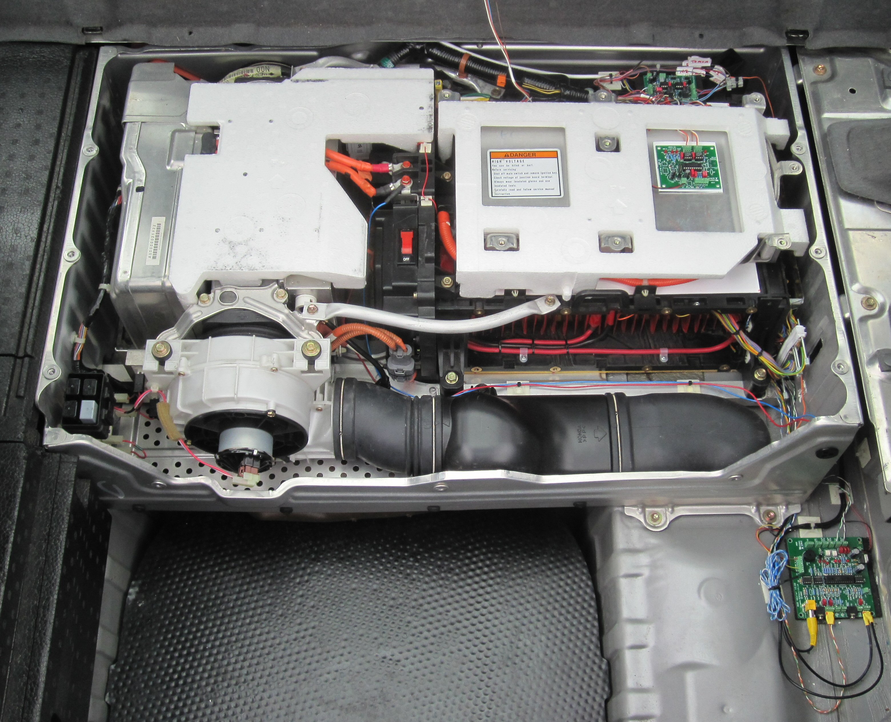
All installed in my 240,000 mile car, and just got back from a 20 mile test, no obvious issues, using lots of assist and regen battery temp rose about 2C during trip.
Cells all within 40mv of each other which is about limit of reliable BMS resolution.
Off out for dinner in it now as a reward!
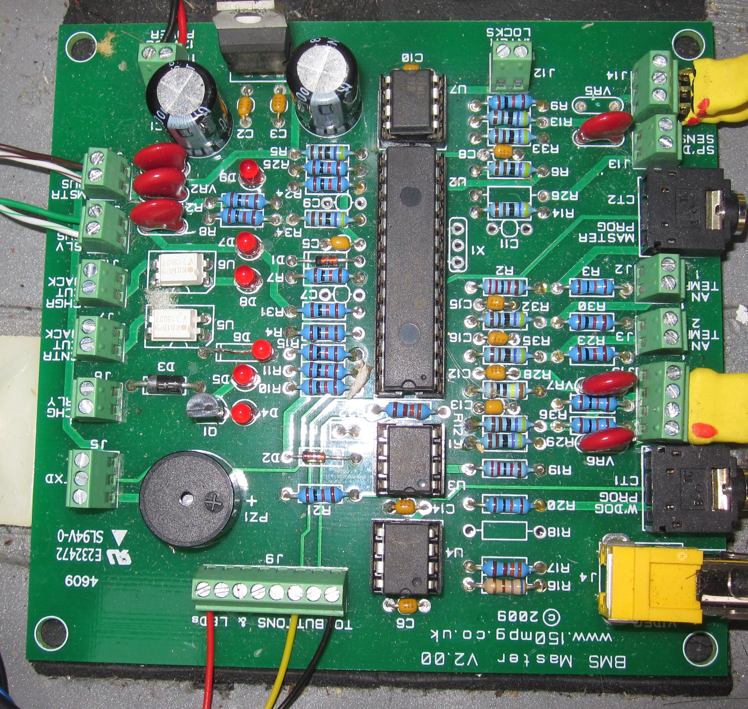
Two large pics and one video to follow.
http://www.solarvan.co.uk/A123/A123Finished017.jpghttp://www.solarvan.co.uk/A123/A123Finished015.jpg This is the master board close up for Greg/Martin
http://www.youtube.com/watch?v=VVAd5_wTMWg