I like that idea. Will soon post what I have been working on regarding a BMS, I know I said last week, but hopefully this week. Still working on a few bugs.
Greg
Moderators: GregsGarage, retepsnikrep
retepsnikrep wrote:Bit of a glitch with cell deliveryI now expect them next Monday.
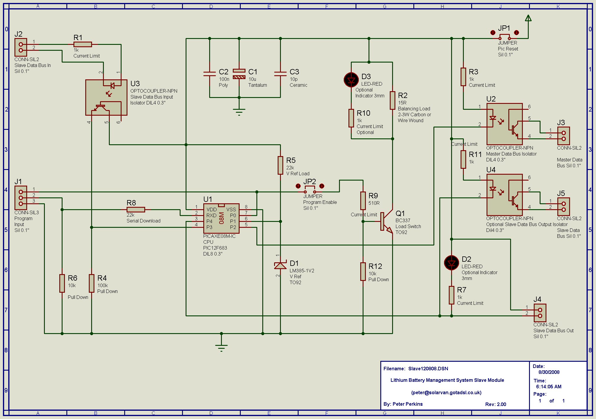
retepsnikrep wrote:Anyway, I've adapted the Slave boards to be dual purpose.
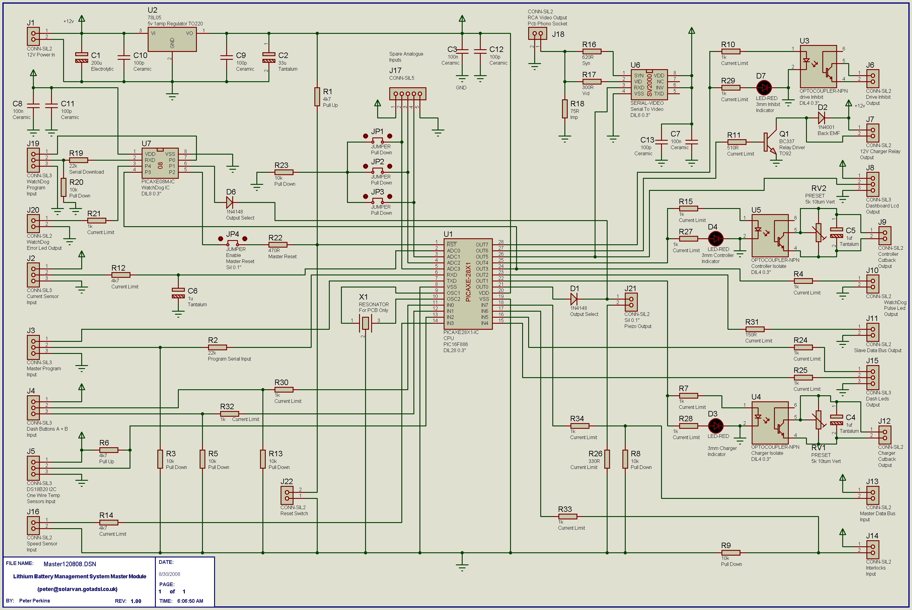
Depending on how you assemble the Slaves (using the same components) you can have the Analogue style solution with an opto for over and under V and on board balancing load, or they can be configured for use with the Master Board, with Master Data Bus, Slave Command Bus and on board balancing/bypass load.
GregsGarage wrote:retepsnikrep wrote:Anyway, I've adapted the Slave boards to be dual purpose.
Depending on how you assemble the Slaves (using the same components
Would it be possible to build the slaves with both options (ie, J2, R1, U3 and J5, U4, R11) and then load the correct program (and maybe set a jumper)? I am thinking that the analogue version would work with what I am trying to do and since I just "let the smoke out" of one of my boards, I might explore that option.
Greg
Users browsing this forum: No registered users and 6 guests

